A Control Plan Template Your Shop Floor Will Actually Use
A process control plan template based on the AIAG Control Plan Manual, with example rows, a review checklist and a revision log.

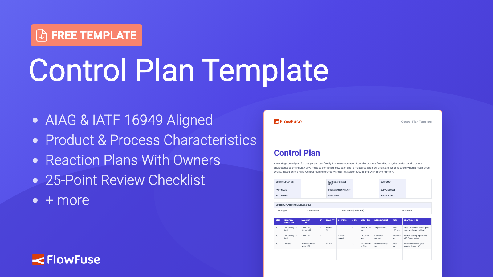
- One row per characteristic: A step with three characteristics gets three rows, each with its own method, frequency and reaction plan.
- Set frequency by volume: "Every 125 parts" tells you which parts are suspect after a failed check. "Every hour" does not.
- Reaction plans need an owner: Contain suspect product, stop the process, restore control and name who does it.
A control plan only works if the people on the line can act on every row without asking anyone what it means. Most of that comes down to how each row is written: what is measured, with which gauge, how often and what to do when a check fails.
This template follows the AIAG Control Plan Reference Manual, 1st Edition (2024), and the minimum content in IATF 16949 Annex A. For background on what a control plan does and how it connects to measurement data, see our guide to control plans.
Download the free control plan template (Word) below. It includes example rows, a 25-point review checklist and a revision log.
Choosing the Phase
The first decision is in the header. It asks you to mark one of four phases, and the phase decides how much control the plan carries:
- Prototype covers dimensional measurements, material and performance tests while the part is still built on prototype tooling.
- Pre-launch covers the extra checks used after prototype and before full production.
- Safe launch is part of pre-launch in the AIAG manual. It adds temporary controls, such as higher sampling frequency or 100% inspection of selected characteristics, for the first weeks of production.
- Production is the plan the line runs once launch is complete.
If you mark safe launch, fill in the exit criteria in the header. A common form is "90 days with no customer issues and no defects found by the additional controls", but use whatever the customer agrees to. Without written exit criteria, nobody can say when the extra checks should end. Once the phase is set, the rest of the work happens in the table.
Writing the Rows
Before filling in the table, gather the current process flow diagram, PFMEA, drawing at the current change level, special characteristics list, MSA results and customer-specific requirements. The rows are built from those documents, so starting without them usually means guessing at values that already exist somewhere else.
Each row describes one characteristic at one process step. If step 20 controls an outer diameter, a face runout and a spindle speed, it takes three rows, and each row is read across from left to right.
Start with the step number and operation, using the same numbers and names as the process flow diagram and PFMEA. Mismatched step numbers are a common audit finding and make failures harder to trace. Next to it, name the machine, jig or tooling with its ID, such as "Press P-03, die D-221" rather than "press". That ID is what links the row to a calibration record or a PLC tag.
The characteristic itself gets a number that traces back to the balloon on the drawing or the line in the PFMEA. It then goes in either the product or the process column. Product characteristics are features of the part, such as a diameter or a leak rate. Process characteristics are the settings that produce them, such as weld current or cycle time. Where a special characteristic depends on a process parameter, give the parameter its own row with its limits.
Special characteristics are marked in the class column with the customer's symbols, such as CC for critical and SC for significant, and the column is left blank for standard characteristics. The specification and tolerance come straight from the drawing at the current change level, with units.
The remaining columns describe how the characteristic is checked. For the measurement technique, name the gauge or test equipment with its ID. Every gauge named here needs an acceptable MSA study, so naming the exact instrument tells you which study to look for. The control method says how the check is managed: a check sheet, an Xbar-R chart, a set-up sheet with first-off approval or a poka-yoke device. For error-proofing, also say how and how often the device itself is verified, for example with a master part at the start of each shift.
Sample Size and Frequency
Sample size is how many parts are checked each time, and frequency is how often the check happens. Where a check is not 100%, express frequency in volume: every 125 parts or every coil. When a check fails, the first question is which parts are suspect, and a volume-based frequency answers it directly. "Every two hours" on a line that runs at different speeds leaves you working backward through production logs to estimate the count.
Some characteristics depend on how the machine was set up, so they need checks tied to the set-up as well. Add a first-off part check after every set-up or tool change, and a last-off part check where the customer requires it.
Characteristics covered by 100% visual inspection need their conditions written down: boundary samples, lighting and how long one inspector stays on the task. Without them, visual inspection catches far less than 100% of defects. However the check is sampled, the row still needs to say what happens when it fails.
Writing the Reaction Plan
The reaction plan is the column most often reduced to "notify supervisor" or "adjust machine". A usable reaction plan covers three steps:
- Contain suspect product, back to the last good check.
- Stop making more of it.
- Restore control and verify it before restarting.
Each plan also names an owner, or references the work instruction that does. If the instructions are long, keep the control plan entry short and point to the document number.
Reactions shouldn't wait for a bad part. A run of points trending toward a limit on an SPC chart, or Cpk dropping below the customer requirement, should start a reaction before anything is out of tolerance. For what to do with parts already made, see containment actions.
Control Plan Template Example
Step 50 on a stamped steel bracket line projection-welds a nut onto the part. The drawing marks the weld nut push-out force as a critical characteristic, and it takes two rows to control:
| Step | Operation | Equipment | No. | Product | Process | Class | Spec | Measurement | Size | Freq. | Control method | Reaction plan |
|---|---|---|---|---|---|---|---|---|---|---|---|---|
| 50 | Projection weld nut | Welder W-02, electrode set E-14 | 11 | Nut push-out force | CC | Min 4.5 kN | Push-out tester PT-1 | 3 pcs | Start of shift + every 400 pcs | Check sheet, destructive test | Stop. Quarantine back to last good test, inspect electrodes, retest 5 pcs. Owner: QE (WI-205) | |
| 50 | Projection weld nut | Welder W-02 | 12 | Weld current | CC | 11.0 ±0.5 kA | Weld controller monitor | 100% | Each weld | Controller limits, auto-reject | Out of window: part auto-rejected. 3 rejects in 50 welds: stop, check electrode wear. Owner: setter |
The first row checks the result on the part, and the second controls the parameter that produces it on every weld. The push-out test scraps the part, so it can only run on a sample, and the 100% current monitoring carries most of the protection between tests. The PFMEA should show the same reasoning, with weld current as the prevention control and the push-out test as the detection control.
Before the plan is released, the review checklist in the template checks this kind of agreement across every row. Run it with the cross-functional team before each phase release and after each update, and treat each "No" as a gap to close before the plan reaches the floor or the customer. Mark N/A only when a check really doesn't apply, and write down the reason.
The checks marked with a dot depend on production or measurement data, such as capability, MSA results and error-proofing verification. They go out of date first because the line changes while the documents stay the same. That is why a released plan needs regular reviews.
Keeping the Plan Current
IATF 16949 clause 8.5.1.1 lists the events that require a control plan review:
- Nonconforming product shipped to the customer
- A change to the product, process, measurement, logistics or supply source
- A change in production volume
- A change to the PFMEA
- A customer complaint and its corrective action
- A scheduled review, at a frequency based on risk
Record each review in the revision log, including reviews that found nothing to change. Then check that the work instructions and check sheets at the stations match the new revision. Layered process audits are a practical way to confirm the plan is followed between formal reviews.
Connecting the Plan to Production Data
Most rows in a control plan point at data the plant already collects. Gauge readings sit in the CMM or SPC software, while process parameters and set-up records live in the PLCs and the MES. The control plan sits in a separate document, so proving it was followed means pulling exports from each system and matching them to rows by hand, usually when an auditor or a customer asks.
FlowFuse closes that gap by connecting to the equipment directly, over OPC UA, Modbus, S7, MQTT and other industrial protocols, and checking each reading against the control plan row it belongs to. In the weld nut example above, that means:
- Weld current is read from W-02's controller on every weld and stored with the part, so the 100% check in row 12 has a record behind it.
- The push-out tests in row 11 are counted against parts produced, and the QE is alerted when 400 parts pass without one.
- A third reject within 50 welds notifies the setter directly, without waiting for someone to notice the reject bin.
- When the plan's revision changes a limit, the new limit is applied in one place and the revision log shows when it reached the line.
The same applies to the dot-marked rows in the review checklist. Capability, error-proofing verification and set-up checks come from live data, so they are current at every review instead of the last time someone updated the binder. When a falling Cpk or a missed check starts a reaction, the evidence for the audit trail is already there.
Your Control Plan Is Only as Good as the Data Behind It
Connect your shop-floor equipment with FlowFuse to collect process data, detect missed checks and out-of-limit readings, and give your team the evidence it needs to act before quality issues reach the customer.
Frequently Asked Questions
About the Author
Sumit Shinde
Technical Writer
Sumit Shinde is a Technical Writer at FlowFuse specializing in industrial automation and manufacturing. In the past three years, he has built industrial applications and authored more than 100 technical articles covering industrial connectivity, unified data architecture, production metrics, and quality management for modern manufacturing.
Like what you're reading?
Add FlowFuse as a preferred sourceOn the page that opens, check the box next to flowfuse.com to see more of our articles in your Google Search results.
Related Articles:
- End of Line Testing: Your Final Defense Against Defects
- Quality Assurance vs Quality Control: Fixing the Process or Checking the Product
- Buyer's Guide: How to Evaluate an Edge AI Platform for Industrial Use
- CQI-9 Heat Treat Audit: A Drifting Thermocouple Can Fail the Whole Furnace
- PPAP Checklist: Free Template and How to Review a Submission