How to Deploy a Basic OPC-UA Server in Node-RED - Part 1 (2026)
OPC-UA Server Information Modeling in Node-RED
This first installment in an OPC UA series explains the OPC UA information model how devices are represented as structured node objects rather than raw register values and walks through deploying a working OPC UA server flow in Node-RED using the node-red-contrib-opcua package. Understanding the information model and address-space hierarchy is the key prerequisite before building OPC UA clients or integrations.
This article is the first part of a series of OPC-UA content. Here, we will explain some basic concepts of OPC-UA as they apply to building a server in Node-RED, then walk through and deploy an example OPC-UA Server.
What is OPC-UA?
Open Platform Communications Unified Architecture (OPC UA) is an open, platform independent communication framework frequently utilized in industrial automation, and is considered one of the key protocol standards for Industry 4.0 and Industrial IoT (IIoT). The standard is developed and maintained by a consortium called the OPC Foundation, with recognizable industry names such as Siemens, Honeywell, Microsoft, Beckhoff, SAP, Yokogawa, ABB, Rockwell, and Schneider Electric.
Because of OPC-UA’s wide industry acceptance, it is increasingly becoming natively supported on devices and systems spanning the entirety of the automation pyramid.

Fieldbus Model vs OPC-UA Information Model
As of today, industrial ethernet fieldbuses dominate the field/device-level (level 0) and controller/PLC-level (level 1) of the automation pyramid.

Fieldbuses such as Profinet, Ethernet/IP, and EtherCAT, employ deterministic, real-time communication, which is essential for mission-critical and safety-oriented automation tasks. OPC-UA is most commonly encountered at the SCADA level and above (level 2-4). However, with the inclusion of Time Sensitive Networking (TSN) into the OPC-UA technology stack, OPC-UA can be feasibly used for real-time communication all the way down to the device level.
Traditionally, fieldbus protocols transmit only raw data from field devices (ie, a float to represent a pressure, or a boolean to represent the position of a switch). The fieldbus data gets pushed up the automation stack layer by layer, where eventually it will be converted to a format suitable for IT systems to consume (such as OPC-UA).

In contrast to fieldbus protocols, OPC-UA represents automation data in the form of nodes. The framework for constructing nodes is referred to as the OPC Information model, and consists of pre-defined classes and methods that are programmed in the OPC Server address space.

/Root/Objects/Calcinator 1 PLC/Temperature Transmitters/Tank 1 Temperature/Transmitter Value
This folder structure will be exposed via the OPC Client browser, allowing end-users to easily “drill down” to individual node information in a logical manner.


The OPC client simply needs to subscribe to the OPC Server endpoint url (ex. opc.tcp://server.address), and the client will be able to browse the structured OPC data as it’s modeled in the server. Any client will receive the information in the same manner, regardless if it’s a PLC, SCADA, MES, or ERP system. This opens the possibility for horizontal and vertical system integration in a standardized manner. Additionally, the more information that is exposed about a device, the easier it is to track, and use said data to autonomously reconfigure, or pre-emptively take maintenance actions.
Deploying an Example OPC-UA Server in Node-RED
With some background on OPC-UA and how information is modeled in mind, we can take a look at the node-red-contrib-opcua-server node, which is merely a compact version of the node-red-contrib-opcua node that only focuses on the OPC-UA server and hence requires less dependencies.
An example flow is provided on github that can serve as a basis for understanding how a OPC-UA server is constructed. Let’s get the example server up and running.
Deploying the example flow yields the following result -

- an inject node is trigging the function
set flow context Inputsat a one second interval, which creates 7 randomly generated float values and stores them as flow context variables,isoInput2-isoInput8(isolated inputs). The values will change to a new random number each time the node is injected.
flow.set('isoInput2', Math.random() + 12.0)
flow.set('isoInput3', Math.random() + 13.0)
flow.set('isoInput4', Math.random() + 14.0)
flow.set('isoInput5', Math.random() + 15.0)
flow.set('isoInput6', Math.random() + 16.0)
flow.set('isoInput7', Math.random() + 17.0)
flow.set('isoInput8', Math.random() + 18.0)

...- another inject node is triggering the function
set flow context Outputs, also at a one second interval, which creates another set of 7 randomly generated float values and stores them as flow context variables,isoOutput2-isoOutput8(isolated inputs). The values will change to a new random number each time the node is injected.
flow.set('isoOutput2', Math.random() + 2.0)
flow.set('isoOutput3', Math.random() + 3.0)
flow.set('isoOutput4', Math.random() + 4.0)
flow.set('isoOutput5', Math.random() + 5.0)
flow.set('isoOutput6', Math.random() + 6.0)
flow.set('isoOutput7', Math.random() + 7.0)
flow.set('isoOutput8', Math.random() + 8.0)

...
We can confirm the values are being stored in memory by checking the flow context data and pressing the refresh button.


The last, and most important part of the flow, is the Compact-Server node, which actually stands alone without any incoming or outgoing connections.

Compact-Server node properties, the first tab is Settings, and the two important properties here are Port and Show Errors. As can be seen in the node screenshot above, the node is reporting active, which means the server is configured correctly.

The Limits tab specifies some default limits that we can configure if we like, but are not necessary to be modified for test purposes.
The Security tab has one important option, Allow Anonymous. By default, anonymous access is enabled.

Users & Sets tab is related to security and permissions. We can leave this empty for testing.
The Address Space tab is where our server OPC Information Model is constructed, using classes and methods from the node-opcua sdk.
Breaking down the provided example code for further context, it starts with a function that is responsible for invoking the OPC-UA server,
const opcua = coreServer.choreCompact.opcua;and then the namespace is created.
const namespace = addressSpace.getOwnNamespace();Further down, the variables that will be published by the server (which are our isoInput & isoOutput flow context variables) are initialized,
  this.sandboxFlowContext.set("isoInput1", 0);
  this.setInterval(() => {
    flexServerInternals.sandboxFlowContext.set(
      "isoInput1",
      Math.random() + 50.0
    );
  }, 500);
  this.sandboxFlowContext.set("isoInput2", 0);
  this.sandboxFlowContext.set("isoInput3", 0);
...
and an OPC folder structure is defined.
  coreServer.debugLog("init dynamic address space");
  const rootFolder = addressSpace.findNode("RootFolder");

  node.warn("construct new address space for OPC UA");

  const myDevice = namespace.addFolder(rootFolder.objects, {
    "browseName": "RaspberryPI-Zero-WLAN"
  });
...
Then, with our variables and folder structure defined, nodes are added to the namespace for each context variable.
const gpioDI1 = namespace.addVariable({
"organizedBy": isoInputs,
"browseName": "I1",
"nodeId": "ns=1;s=Isolated_Input1",
"dataType": "Double",
"value": {
"get": function() {
return new Variant({
"dataType": DataType.Double,
"value": flexServerInternals.sandboxFlowContext.get("isoInput1")
});
},
"set": function(variant) {
flexServerInternals.sandboxFlowContext.set(
"isoInput1",
parseFloat(variant.value)
);
return opcua.StatusCodes.Good;
}
}
});
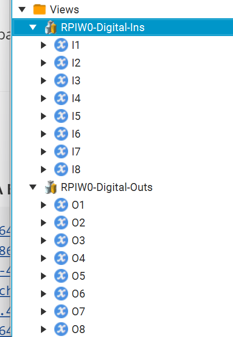
...Last, OPC views are defined. Views create custom hierarchies our OPC Client can browse as an alternative to the default folder structure.
  const viewDI = namespace.addView({
    "organizedBy": rootFolder.views,
    "browseName": "RPIW0-Digital-Ins"
  });

  const viewDO = namespace.addView({
    "organizedBy": rootFolder.views,
    "browseName": "RPIW0-Digital-Outs"
  });

  viewDI.addReference({
    "referenceType": "Organizes",
    "nodeId": gpioDI1.nodeId
  });

...
Finally, on the Discovery tab, we must define an endpoint for an OPC Client to subscribe to.
The Endpoint Url follows the format opc.tcp://<address>:port. Our port was defined on the Settings tab, which by default, is port 54845. The address will be either the url or ip address of your Node-RED instance. In my case, it’s 192.168.0.114. So my Endpoint Url = opc.tcp://192.168.0.114:54845


Connect to Example OPC-Server Using OPC-UA Browser
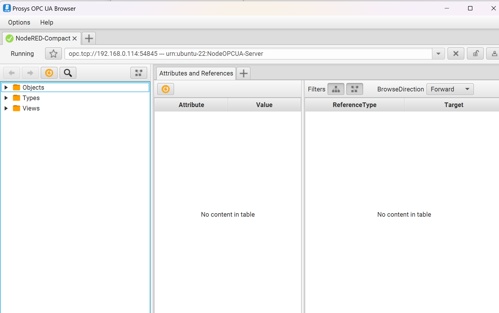
To connect to our OPC endpoint, we need an OPC Client. Prosys provides a free OPC-UA Browser that supports Windows, Linux, and Mac OS. To test our Server, the Windows version of Prosys OPC-UA Browser will be utilized.
To connect to our Node-RED OPC server, enter the endpoint url and press “connect to server”.

None is the correct option.
Once connected, we can browse our OPC Server.
Objects → RaspberryPI-Zero-WLAN → GPIO → Inputs, we can see a list of inputs that correspond to the isoInput context variables defined in the example flow, which are randomly generated numbers.
Clicking I1 we can see the value in real-time, along with some additional properties.

Views, we can see the custom hierarchy defined in the example server, which divides the data by Digital-Ins and Digital-Outs.
Summary
In this article, we compare OPC-UA to traditional fieldbus protocols, explain the importance of the OPC UA Information Model to understand how data is modeled in the address space of an OPC Server, and then walk through and deploy an example compact OPC-UA Server flow.
In our next article, we will build a custom OPC-UA Server in Node-RED with data pulled from an Allen Bradley PLC over Ethernet/IP, using the PLC data to develop a custom OPC UA Information Model programmed in the OPC server address space.
Run Your OPC UA Node-RED Server in the Cloud
Sign up for FlowFuse to deploy, manage, and scale your Node-RED OPC UA server flows securely in the cloud with built-in DevOps pipelines.
Frequently Asked Questions
Table of Contents
Like what you’re reading?
Add FlowFuse as a preferred sourceOn the page that opens, check the box next to flowfuse.com to see more of our articles in your Google Search results.
Related Articles:
- Bridging OPC UA Data to MQTT with Node-RED (2026)
- How to Build an OPC UA Client Dashboard in Node-RED - Part 3 (2026)
- Node-RED Serial Port Tutorial: Connect RS232/RS485 Manufacturing Equipment (2026)
- How to Read and Write Siemens S7 PLC Data — A Node-RED Guide (2026)
- Interacting with ESP32 Using Node-RED and MQTT (2026)