Store-and-Forward at the Edge: Buffering Production Data During Network Outages
Keep collecting data when your network goes down
Network outages happen. A fiber cut, a switch failure, or infrastructure maintenance can take your connectivity offline without warning. When it does, your PLCs continue operating normally—they don't wait for the network to recover.
The problem is that all the data they generate during that outage has nowhere to go. Production metrics, quality measurements, and alarm events accumulate with no path to your historian or cloud platform. When connectivity returns, you're left with gaps in your operational records. Those gaps create real problems: incomplete batch records for quality audits, missing data for troubleshooting production issues, and compliance documentation that doesn't hold up under review.
Store-and-forward solves this. This article walks through building a store-and-forward system with FlowFuse that maintains complete data continuity during network failures.
Below is the demo video where I show how production data can be lost without buffering, and how buffering prevents that from happening.
What is Store-and-Forward?
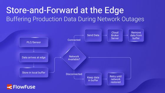
Store-and-forward is a pattern where data is saved locally before transmission, then forwarded when network connectivity is available. Your edge device writes every data point to local SQLite storage first. If the network is up, the data transmits to your destination—MQTT broker, historian, cloud platform, or database. If the network is down, the data stays in storage until connectivity returns.
The edge device operates in three states. During normal operation, data writes to the buffer and forwards successfully—the buffer stays near-empty. During a network outage, data continues writing to the buffer but cannot forward—the buffer grows. When connectivity returns, the device forwards the buffered backlog in chronological order while continuing to collect new data—the buffer drains back to empty.
flowchart TD
    Source[PLC / Sensor]
    Destination[Cloud / Broker / Server]

    Source --> Start[Data Arrives at Edge]
    Start --> Save[Store in Local Buffer]
    Save --> Check{Network Available?}

    Check -->|Connected| Send[Send Data]
    Send --> Destination
    Destination --> Clear[Remove Data from Buffer]

    Check -->|Disconnected| Wait[Keep Data in Buffer]
    Wait --> Retry[Retry Until Network Restored]
    Retry --> Check

    %% Styling (consistent theme)
    style Source fill:#3B82F6,color:#fff
    style Start fill:#3B82F6,color:#fff
    style Save fill:#818CF8,color:#fff
    style Check fill:#6366F1,color:#fff
    style Send fill:#60A5FA,color:#fff
    style Destination fill:#60A5FA,color:#fff
    style Clear fill:#93C5FD,color:#000
    style Wait fill:#A5B4FC,color:#fff
    style Retry fill:#BFDBFE,color:#000
This solves the core problem in industrial data collection: network failures creating gaps in your time-series data. A four-hour outage would normally mean four hours of missing production data. With store-and-forward, that same outage causes zero data loss. Your destination system receives complete chronological data with only a delivery delay.
Getting Started
Let's build a store-and-forward system to protect your data during network outages.
We'll approach this in six steps: establish a connection to collect data, set up a local buffer to temporarily store that data, write incoming data to the buffer, monitor network connectivity status, create forwarding logic to transmit buffered data when connectivity returns, and finally add error handling and buffer management to ensure reliable operation.
Prerequisites
You'll need the following before implementing store-and-forward:
- Edge Device Running FlowFuse Agent: A running FlowFuse instance deployed on your edge hardware or gateway device.
- node-red-node-sqlite: SQLite node for local data storage.
- node-red-contrib-ping: Ping node for connectivity monitoring.
Step 1: Set Up Data Collection
Data collection is the foundation of store-and-forward. Your edge device needs reliable connectivity to your data sources before you can buffer and forward their data.
FlowFuse handles this through Node-RED's 5,000+ community nodes, which support virtually every industrial protocol and interface—Modbus, OPC UA, MQTT, Ethernet/IP, GPIO pins, serial connections, and more. You collect data from your sources, transform it into the format you need, and prepare it for buffering.
For this guide, we'll assume you already have data flowing into FlowFuse. The store-and-forward pattern works the same regardless of which data sources or protocols you're using.
For more information on how FlowFuse can help you connect, collect, transform, and contextualize your data, and how it simplifies deployment, management, scaling, and security with enterprise features for production environments, book a demo.
Step 2: Implement SQLite Buffering
SQLite provides the persistent storage layer for your store-and-forward buffer. It's lightweight, requires no separate database server, and handles the write volumes typical of industrial data collection without issue.
Follow these steps to set up your SQLite buffer:
-
Drag the sqlite node from the palette onto your workspace.
-
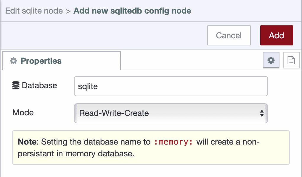
Double-click the node to open its configuration panel. Click the pencil icon next to the Database field to create a new database configuration. Give it a name like sqlite, select Read-write-create as the mode, and click Add to save the configuration.
- Set the SQL Query mode to Fixed Statement. In the SQL Query field, enter:
CREATE TABLE IF NOT EXISTS data_buffer (
    id INTEGER PRIMARY KEY AUTOINCREMENT,
    timestamp INTEGER NOT NULL,
    sent INTEGER DEFAULT 0,
    payload TEXT,
    created_at INTEGER DEFAULT (strftime('%s','now') * 1000)
);
The payload stores the serialized data as JSON. The sent flag indicates whether the record is still pending (0) or has been successfully delivered (1) — this acts as a safety marker to prevent cleanup of unsent data.
- Connect an Inject node to Sqlite node
- Deploy your flow and click the inject node button to create the table.
Your SQLite buffer is now ready to store data during network outages. The next step implements the logic to write incoming data to this buffer.
Step 3: Store Incoming Data in Buffer
With your SQLite buffer ready, implement the logic to write incoming PLC data to storage.
-
Drag a JSON node onto the canvas and connect it to your data input source.
-
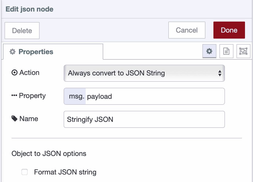
Double-click the node to open its configuration. Set the Action to
Always convert to JSON Stringand set the Property tomsg.payload, then click Done to save.
Note: JSON converts your data object into a text string for storage. If your data source already provides a JSON string (not an object), you must delete this node.
-
Drag a Change node onto the canvas and connect it to the JSON node.
-
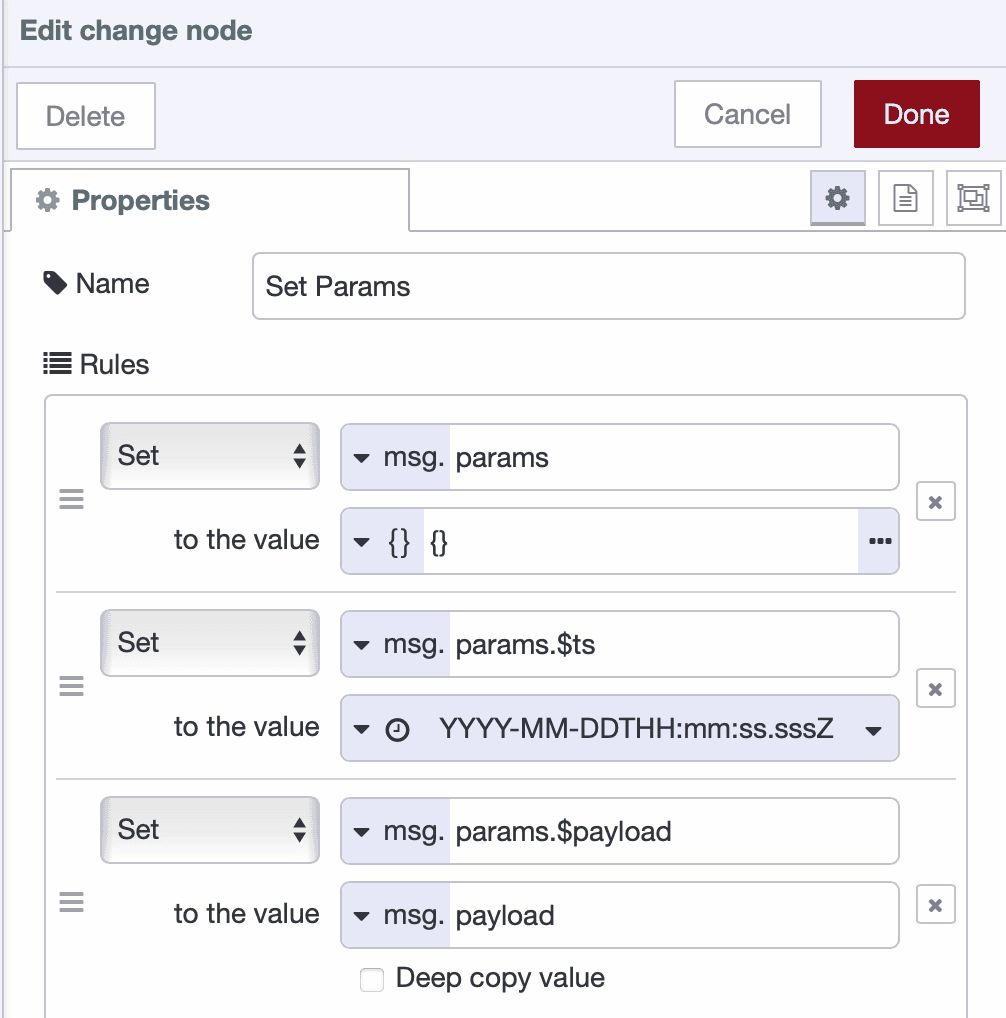
Double-click the Change node to configure it. Add the following rules:
- Rule 1: Set
msg.paramsto{}(JSONata expression) - Rule 2: Set
msg.params.$tstomsg.timestamp - Rule 3: Set
msg.params.$payloadtomsg.payload
- Rule 1: Set
-
Drag another Sqlite node onto the canvas and connect it to the Change node.
-
Double-click the node to configure it. Select your existing Sqlite database, set the SQL Query mode to
Prepared Statement, and in the SQL Query field, enter:
INSERT INTO data_buffer (timestamp, payload, sent)
VALUES ($ts, $payload, 0);- Click Done to save the configuration and deploy your flow.
Your buffer now accumulates all incoming data. Each data point is serialized to JSON, structured into parameters, and written to SQLite with sent=0 (not yet forwarded). The prepared statement approach prevents SQL injection issues and handles special characters correctly.
Step 4: Monitor Network Connectivity
Network connectivity monitoring determines when your system can forward buffered data. The ping node checks connectivity to your destination system, and when the network is available, it triggers the forwarding process.
Follow these steps to implement connectivity monitoring:
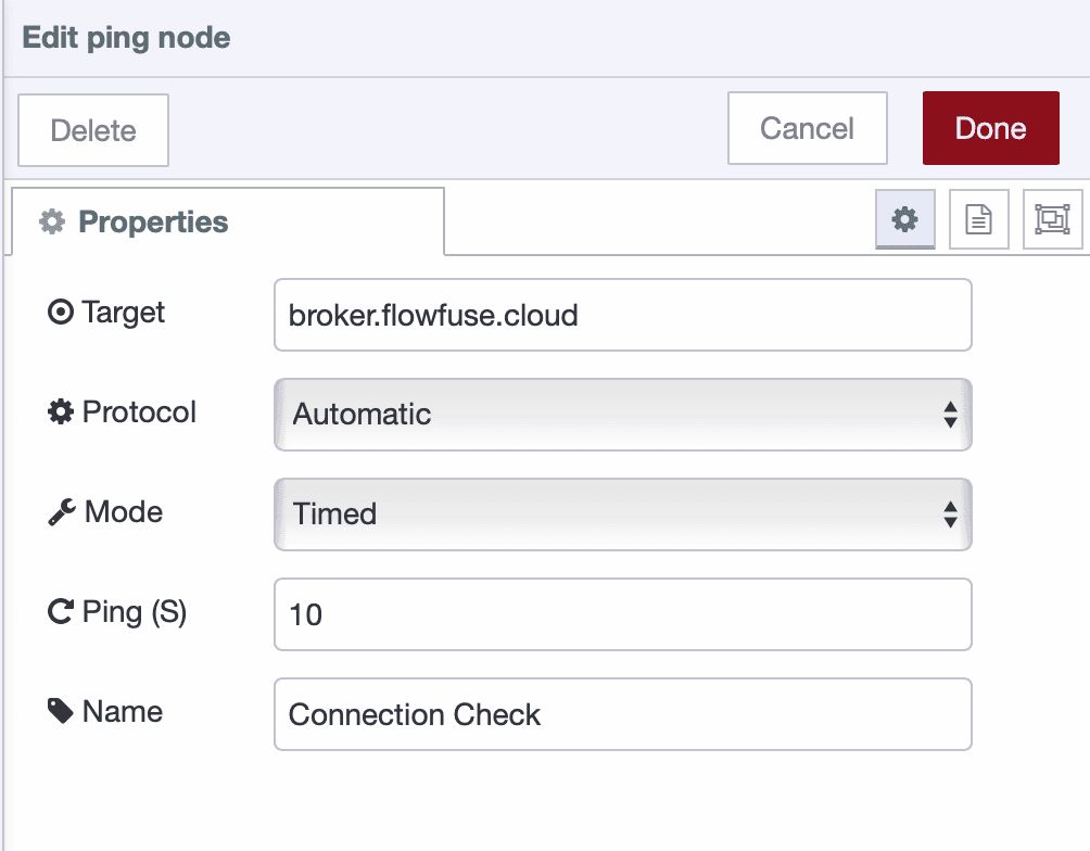
-
Drag a Ping node onto the canvas.
-
Double-click the node to configure it. Enter the IP address or hostname of your destination system in the Target field (e.g.,
broker.flowfuse.cloud), select mode to "Automatic", set "Ping every" to30seconds (adjust based on your requirements), name it "Network Health Check", and click Done to save.
-
Drag a Switch node onto the canvas and connect it to the Ping node.
-
Double-click the Switch node to configure it. Set the Property to
msg.payload,- add Rule 1 as
false(network is down), - add Rule 2 as
otherwise(network is reachable).
- add Rule 1 as
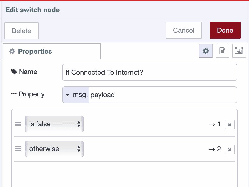
- Click Done to save.
The switch node routes messages based on ping results. When ping fails, msg.payload is false. Otherwise, the ping succeeded with a response time.
-
Drag two change nodes onto the canvas. Connect the first one to output 1 of the switch node (network down), and the second one to output 2 (network reachable).
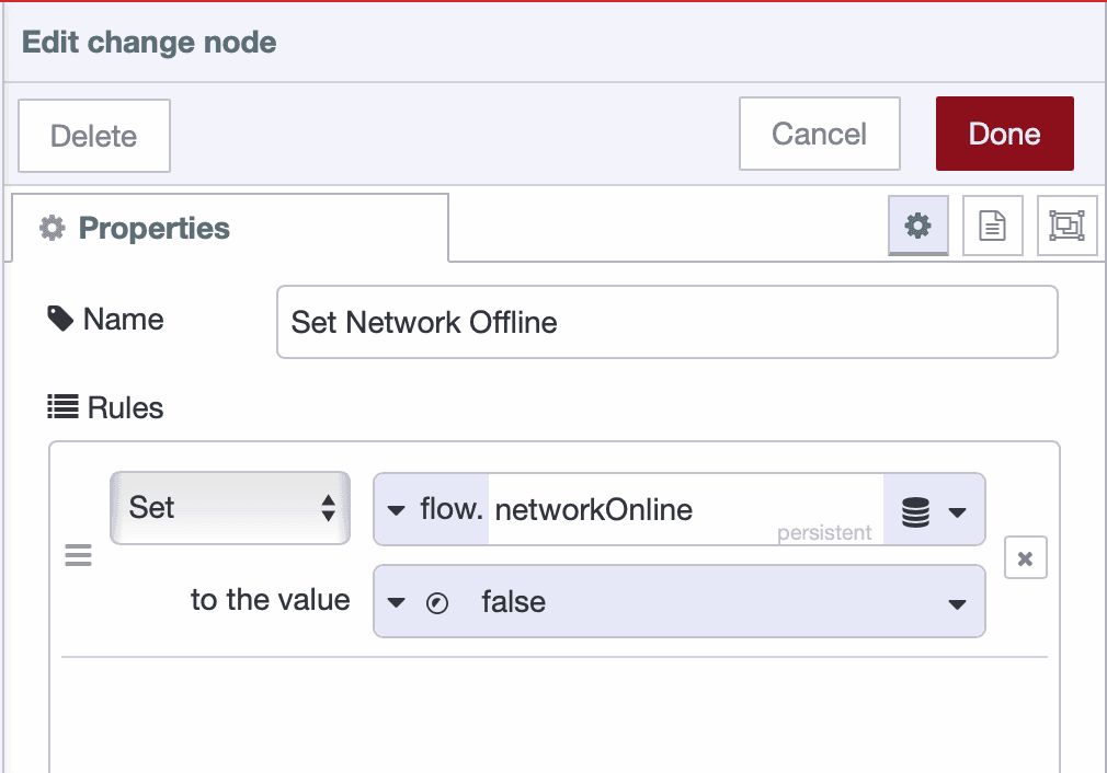
-
Double-click the first change node to configure it:
- Rule 1: Set
flow.networkOnlinetofalse(boolean) ( make sure it is stored in the persistent storage ) - Name it "Set Network Offline"
- Click Done to save.
- Rule 1: Set
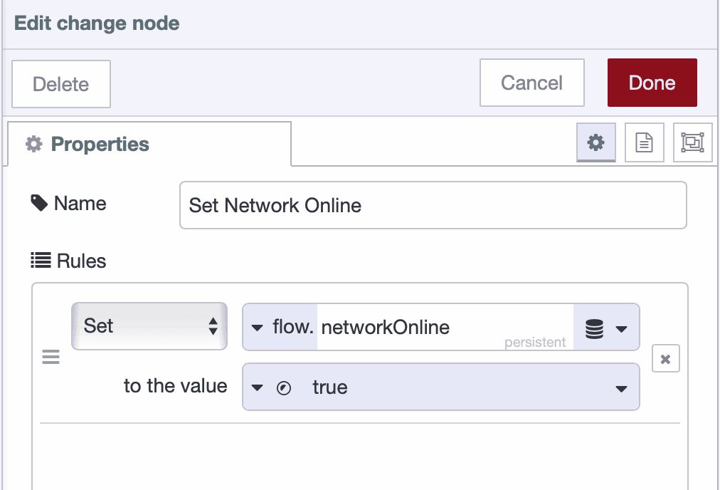
- Double-click the second change node to configure it:
- Rule 1: Set
flow.networkOnlinetotrue(boolean) - Name it "Set Network Online"
- Click Done to save.
- Rule 1: Set
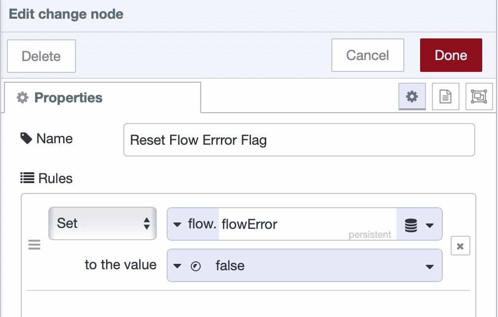
- Drag another change node onto the canvas and configure it:
- Rule 1: Set
flow.flowErrorto false (this resets the error state triggered in the Handle Errors and Disconnections section).
- Rule 1: Set
- Drag a Link Out node onto the canvas and connect it to the "Set Network Online" node. Name it "Trigger Forward".
Your connectivity monitoring is now complete. When the network is available, the system will trigger the forwarding logic to send buffered data.
Step 5: Build the Forwarding Logic
The forwarding logic retrieves unsent data from the buffer, prepares it for transmission, and sends it to the destination. This section shows how to build a forwarding system that processes buffered data in batches.
Retrieve and Prepare Unsent Records
-
Drag a Link In node onto the canvas and name it "Trigger Forward". Link this to the Link Out node from Step 4.
-
Drag an SQLite node onto the canvas and connect it to the Link In node. Name it "Get Unsent Data" and configure it by selecting your database, setting SQL Query mode to Fixed statement, and entering the following SQL:
   SELECT * FROM data_buffer
   WHERE sent = 0
   ORDER BY timestamp ASC
LIMIT 50;-
Click Done to save.
-
Drag a Split node onto the canvas and connect it to the SQLite node. Configure it to split msg.payload and click Done.
-
Drag a Change node onto the canvas and connect it to the Split node. Name it "Prepare Forward Message" and add the following rules:
- Rule 1: Set
msg.record_idtomsg.payload.id - Rule 2: Set
msg.payloadtomsg.payload.payload
- Rule 1: Set

-
Click Done to save.
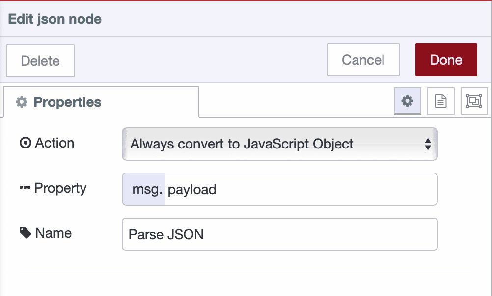
-
Drag a JSON node onto the canvas and connect it to the Change node. Configure it by setting Action to Always Convert to JSON Object and Property to
msg.payload, then click Done.
-
Click Done to save.
-
Drag a Link Out node onto the canvas and connect it to the JSON node. Name it "Send to Destination".
Your forwarding logic now retrieves unsent records, prepares them for transmission, and passes them to the next stage for sending.
Step 6: Send Data and Handle Errors
This step implements data transmission to your destination with comprehensive error handling and buffer management.
Send Data to Destination
-
Drag a Link In node onto the canvas and link it to the Link Out node from Step 5. Name it "Send to Destination".
-
Drag a Switch node onto the canvas and connect it to the Link In node. Name it "Check Network Online", set the Property to
flow.networkOnline, add a conditionis true, and click Done to save.

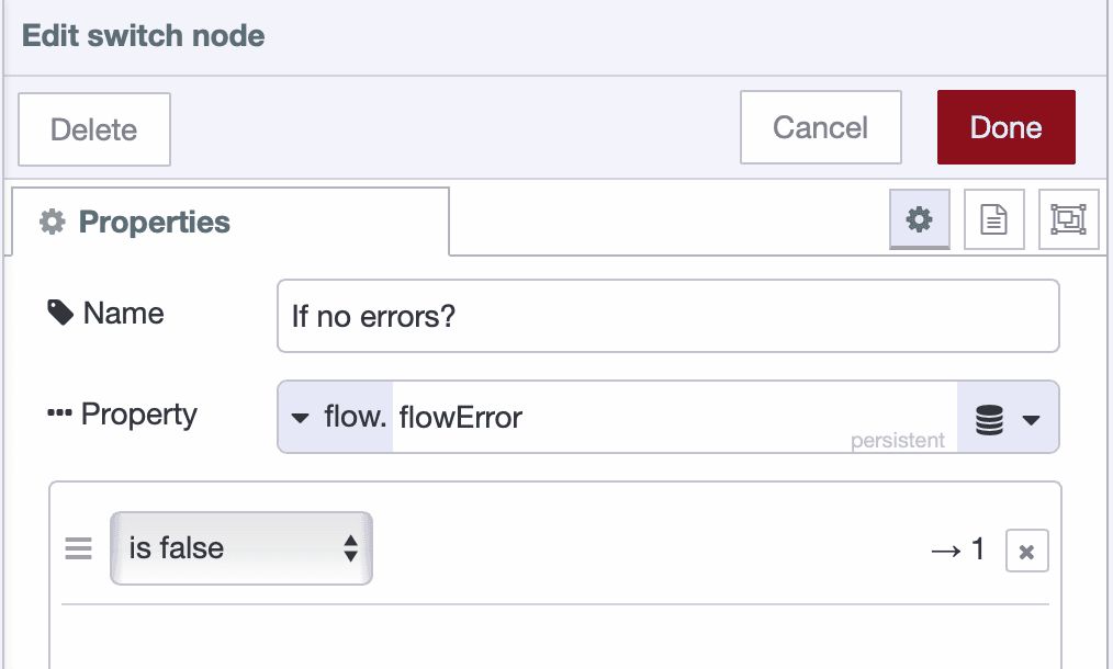
- Drag another Switch node onto the canvas and connect it to the first switch node's output. Name it "Check Flow Error", set the Property to
flow.flowError, add a conditionis false, and click Done to save.
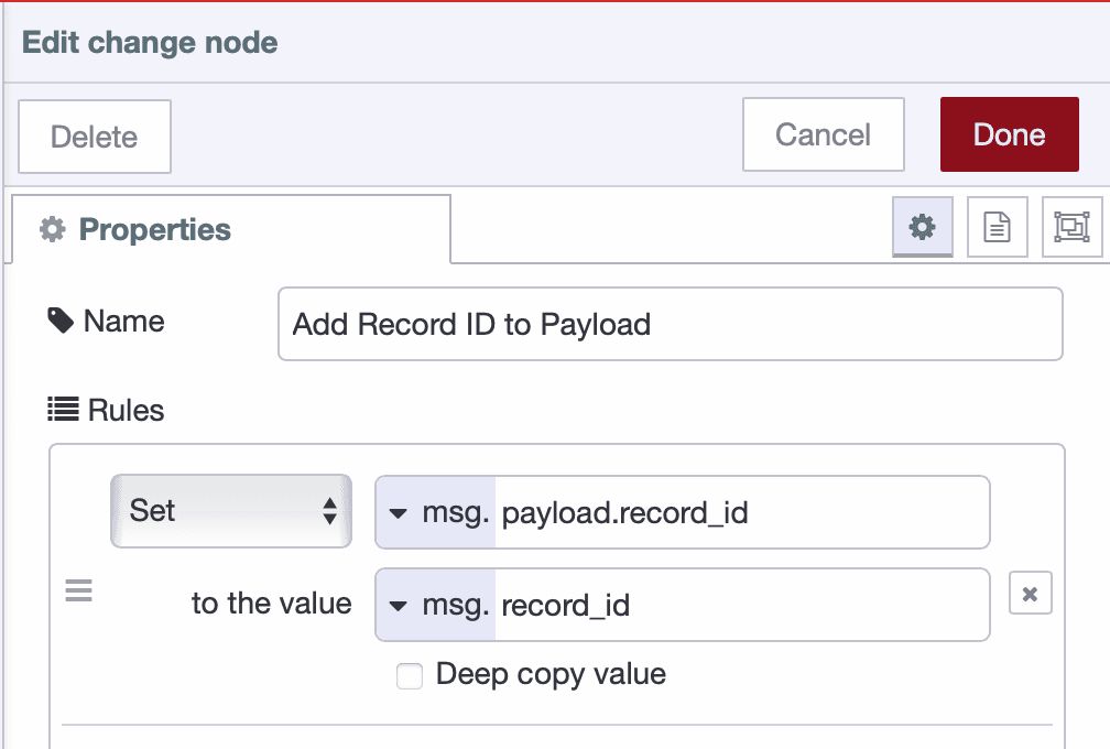
- Drag a Change node onto the canvas and connect it to the second switch node's output. Configure it to append the record ID into the payload for transmission confirmation:
- Rule 1: Set
msg.record_idtomsg.payload.record_id
- Rule 1: Set
- Drag a Project Out node onto the canvas and connect it to the Change node. Double-click the node to open its configuration. Select "Send to specified node" as the mode, then enter select target "broadcast message" and enter topic (for example:
acme_manufacturing/plant_01/floor_2/cell_a/machine_A12/measurements). Click Done to save the configuration.
Note: you can use any output node that suits your architecture instead of Project Out, such as MQTT Out for publishing to MQTT brokers, HTTP Request for sending data to REST APIs, Database nodes for writing directly to databases or other protocol-specific nodes depending on your destination requirements.
- Deploy the flow.
Mark Records as Sent and Clear Buffer
- Drag a Project In node onto the canvas, double-click the node to configure it with source set to "Listen for broadcast messages", and configure it to listen on all instances and devices with the topic that should match the same topic you configured in the Project Out node earlier to subscribe to your data that was sent before.
Note: The Project In node is used here to confirm successful transmission when using Project Out nodes. If you are using other output nodes such as MQTT Out, HTTP Request, or database nodes, replace the Project In node with the corresponding confirmation mechanism for your chosen protocol. For example, if your output node such as HTTP Request responds with a status code or success message, you can use that response directly for confirmation instead of the Project In node.
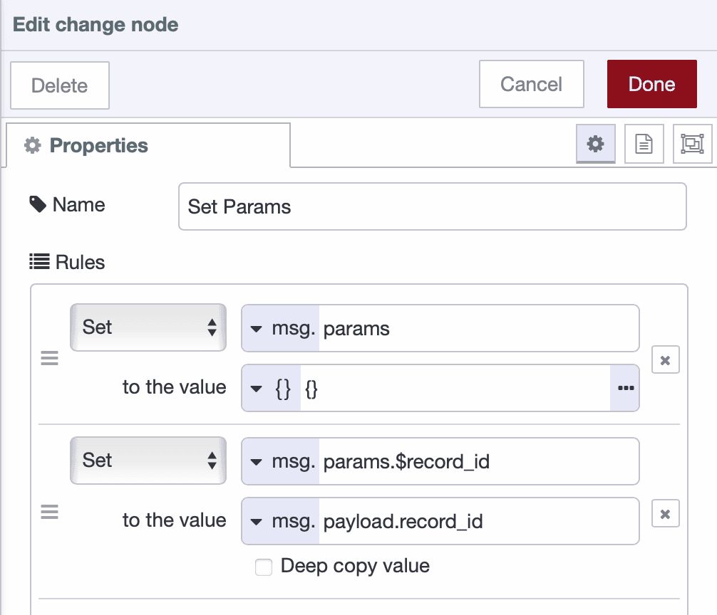
- Drag a Change node onto the canvas and connect it to the Project In node. Name it "Prepare Record ID" and configure the following rules:
- Rule 1: Set
msg.paramsto{}(JSONata expression:{}) - Rule 2: Set
msg.params.$record_idtomsg.record_id
- Rule 1: Set
-
Click Done to save.
-
Drag an SQLite node onto the canvas and connect it to the Change node. Name it "Mark as Sent", then double-click it to configure. Select your database, set SQL Query mode to Prepared Statement, and enter the following SQL:
   UPDATE data_buffer
   SET sent = 1
WHERE id = $record_id;-
Click Done to save.
-
Drag another SQLite node onto the canvas and connect it to the previous SQLite node. Name it "Delete Record", then double-click it to configure. Select database, set SQL Query mode to Prepared Statement, and enter the following SQL:
   DELETE FROM data_buffer
   WHERE id = $record_id
AND sent = 1;- Click Done to save and deploy the flow.
Handle Errors and Disconnections
-
Drag a Catch node onto the canvas. Configure it to catch errors from all nodes.
-
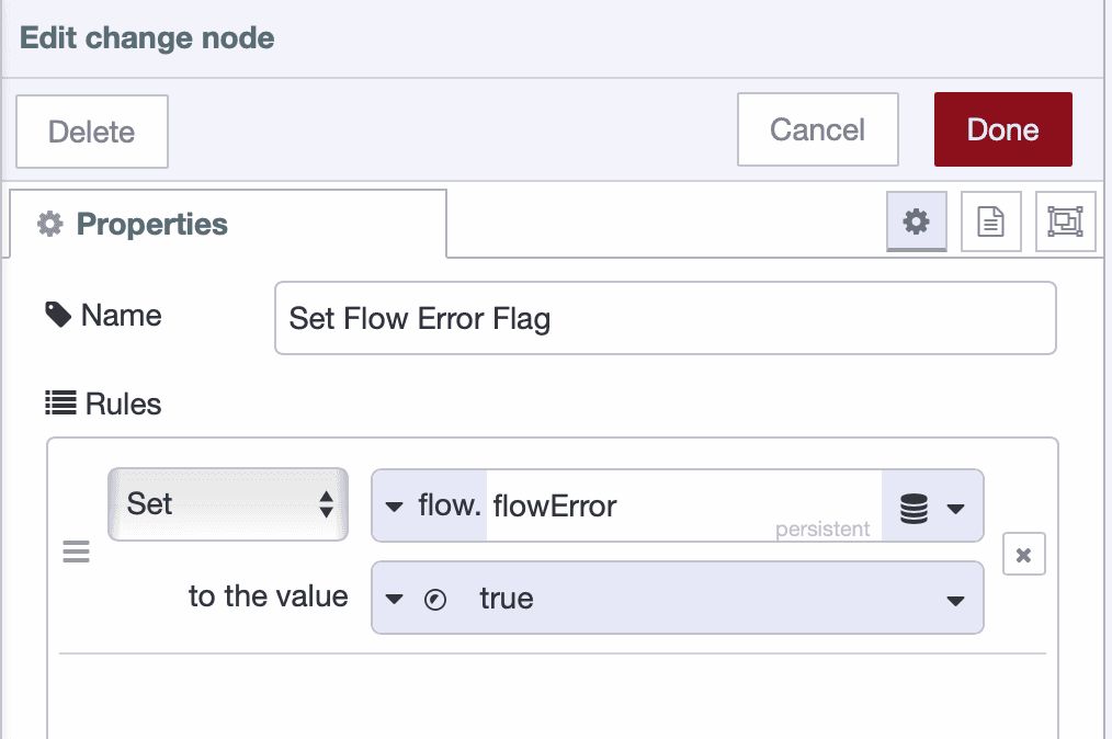
Drag a Change node onto the canvas and connect it to the Catch node.
-
Name it "Set Flow Error" and configure it:
- Rule 1: Set
flow.flowErrortotrue(boolean)
- Rule 1: Set
-
Click Done to save.
-
Drag a Status node onto the canvas and configure it to monitor the Project node's status.
-
Drag a Switch node onto the canvas and connect it to the status node.
-
Name it "Check Disconnected", set the Property to
msg.status.text, add a condition==with valuedisconnected, and click Done to save. -
Drag a Change node onto the canvas and connect it to the Switch node.
-
Name it "Set Network Failure Flag" and configure it:
- Rule 1: Set
flow.networkOnlinetofalse(boolean)
- Rule 1: Set
-
Click Done to save and deploy your flow.
Conclusion
You now have a working store-and-forward system that protects your data during network failures.
When the network is up, data flows through the buffer and transmits immediately. When the network goes down, data accumulates in SQLite. When connectivity returns, the buffered data forwards automatically while new data continues collecting. No data is lost, regardless of how long the outage lasts.
This pattern solves a common problem in industrial environments: maintaining complete time-series data when network infrastructure fails. Your production systems can now operate independently of network reliability.
The system you've built is production-ready as-is, but you can extend it based on your requirements—add monitoring for buffer capacity, implement data validation rules, or configure forwarding to multiple destinations. The core mechanism remains the same.
If you want to get the flow template that you can use directly and modify according to your needs, check out our latest blueprint.
Discuss your use case with our team
See how FlowFuse can support your architecture, integrations, and deployment needs.
About the Author
Sumit Shinde
Technical Writer
Sumit is a Technical Writer at FlowFuse who helps engineers adopt Node-RED for industrial automation projects. He has authored over 100 articles covering industrial protocols (OPC UA, MQTT, Modbus), Unified Namespace architectures, and practical manufacturing solutions. Through his writing, he makes complex industrial concepts accessible, helping teams connect legacy equipment, build real-time dashboards, and implement Industry 4.0 strategies.
Related Articles:
- 5 Places Smart Factories Are Already Using AI
- How to Monitor Industrial Network Health Using SNMP
- Edge vs Cloud AI in Manufacturing: Where Each Actually Belongs
- How to Connect to Beckhoff TwinCAT PLC Using ADS (2026)
- FlowFuse 2.28: Troubleshoot Faster, Manage Edge Devices Centrally, and More Self-Hosted Flexibility