How to Access Optimized Data Blocks in TIA Portal (S7-1200/1500)
Use OPC UA to read optimized data blocks by name instead of fighting with memory addresses
When working with Siemens S7-1200 and S7-1500 PLCs, you’ll notice that TIA Portal creates optimized data blocks by default. Unlike the classic S7-300/400 controllers, optimized blocks do not use fixed memory offsets. Instead, the PLC compiler reorganizes the data internally for better performance and memory efficiency. This architectural change often creates confusion when trying to read PLC data from external systems.
FlowFuse simplifies this challenge by providing a modern way to connect OT and IT systems and build industrial applications using a low-code, drag-and-drop approach. However, reading optimized data blocks still requires a different access method than traditional S7 communication.
You can disable optimization in TIA Portal by unchecking the "Optimized block access" option in your data block properties. This gives you the old-style addressing where you can read data using fixed offsets like DB1.DBW0. However, this approach has several drawbacks. Optimized blocks run faster, use less memory, and follow Siemens' current best practices. If you're working on existing projects with thousands of tags, converting everything to standard blocks isn't practical. Many companies also require optimized blocks as part of their coding standards.
This guide shows you how to read optimized data blocks directly without disabling optimization. You'll learn to use symbolic addressing, which is the proper way to access data from modern Siemens PLCs.
Why Reading Optimized Data Blocks Is Challenging
The S7 Protocol Problem
Traditional S7 communication, which most Node-RED S7 nodes use, relies on absolute memory addresses. You read data by specifying exact locations like DB1,INT0 (read integer at byte 0) or DB5,REAL10 (read real at byte 10).
This worked fine with classic S7-300/400 controllers where memory layout was predictable. If you declared an integer first in your data block, it always started at byte 0. Simple and reliable.
What Optimization Breaks
Optimized data blocks rearrange variables for better performance and memory efficiency. The compiler groups variables by type, adds alignment padding, and reorders declarations. Your variable positions become unpredictable and can change with each recompile.
Example: You create variables Temperature (Real), Status (Bool), Pressure (Real), Alarm (Bool). Instead of sequential storage, the optimizer might group the two Real values together and pack Bools elsewhere. The Status boolean isn't at byte 4 anymore—it could be anywhere.
Why S7 Nodes Fail
Node-RED packages like node-red-contrib-s7 need exact memory addresses. With optimized blocks:
- TIA Portal doesn't show you the actual memory layout
- Offsets can't be reliably determined
- Recompiling your PLC program silently breaks all your addresses
- The S7 protocol has no way to read variables by name
You're stuck guessing at memory locations that keep changing.
The Solution: OPC UA
OPC UA reads variables by name, not memory address. Instead of asking "what's at byte 10?" it asks "what's the value of Temperature_Sensor_01?"
Siemens S7-1200 and S7-1500 PLCs have built-in OPC UA server. Activate it in TIA Portal, mark which variables to expose, and the PLC handles all memory mapping internally. FlowFuse connects and reads data by variable name, regardless of how the PLC organizes memory.
When you modify your data block or recompile, your flows keep working because they reference variable names, not memory locations that might shift.
Prerequisites
Before you begin, make sure you have:
- TIA Portal V13 or later, and you know how to download a program to your PLC
- A Siemens S7-1200 or S7-1500 PLC with OPC UA server support
- A FlowFuse Agent running on your edge device
- The PLC and edge device connected to the same network
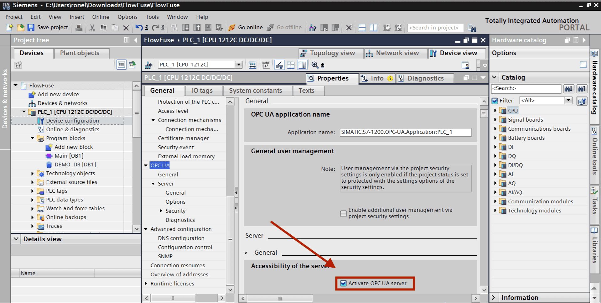
Step 1: Activate OPC UA Server on Your PLC
First, you need to activate the OPC UA server that's built into your S7-1200/1500 PLC.
- Launch TIA Portal and open your project
- In the project tree on the left, select your PLC and double-click it
- Find OPC UA in the device properties (usually under General or Properties section)
- Check Activate OPC UA Server
- Set Port to
4840(the standard OPC UA port) - Set Security Policy to None (for testing only)
- Enable Guest authentication.
Note that we've disabled security entirely in steps 6-7 to get you up and running quickly. This is fine for learning and testing, but don't leave it this way. Before moving to production, configure proper authentication with certificates and user credentials. Get the communication working first, then secure it.
Step 2: Add OPC UA Server Interface
Before exposing variables, you need to create an OPC UA server interface in your PLC configuration.
For S7-1500 PLCs (firmware V2.5 or higher):
If you're using an S7-1500 PLC with firmware version 2.5 or higher, you have the option to enable the standard SIMATIC server interface. Simply check Enable standard SIMATIC server interface in the OPC UA settings. This automatically makes all PLC tags that are marked as accessible available through OPC UA.
For S7-1200 PLCs (or manual configuration for S7-1500):
For S7-1200 PLCs, you must manually create a server interface and add the tags you want to expose:
- In TIA Portal, navigate to OPC UA communication in the project tree
- Right-click on Server interfaces
- Select Add new server interface
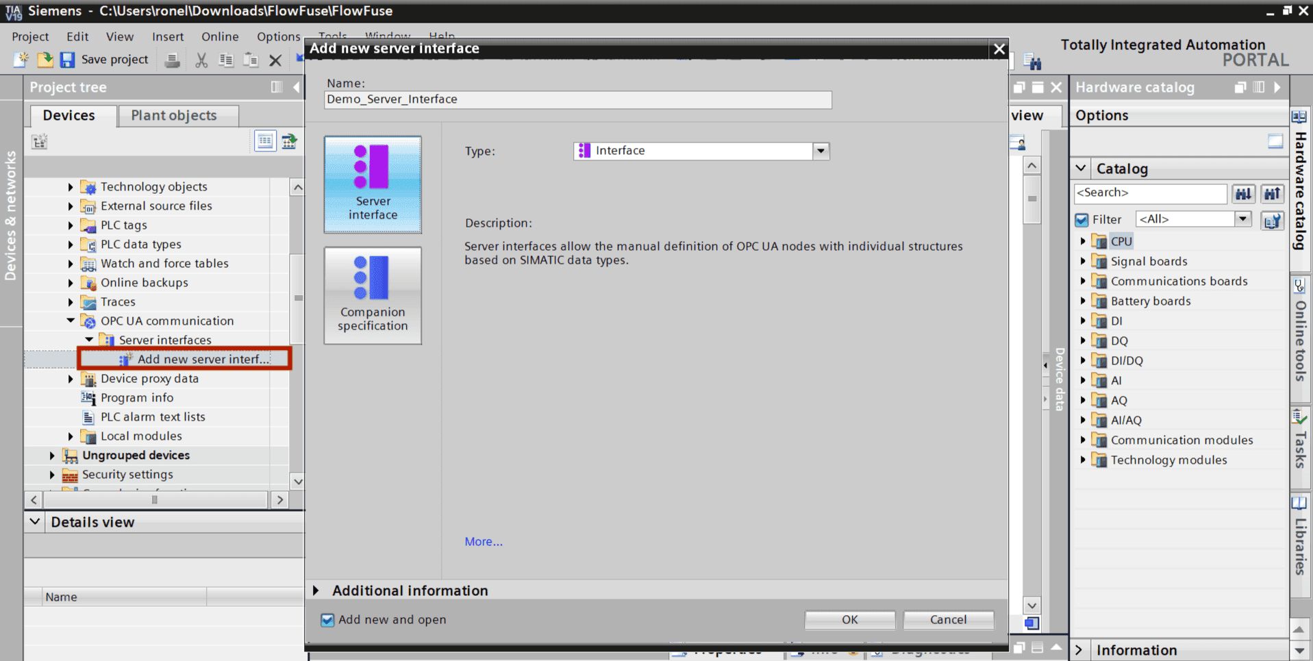
- Leave the default settings and click OK
- The server interface will be created (you can rename it if needed)
Now this interface needs to know which data blocks to expose.
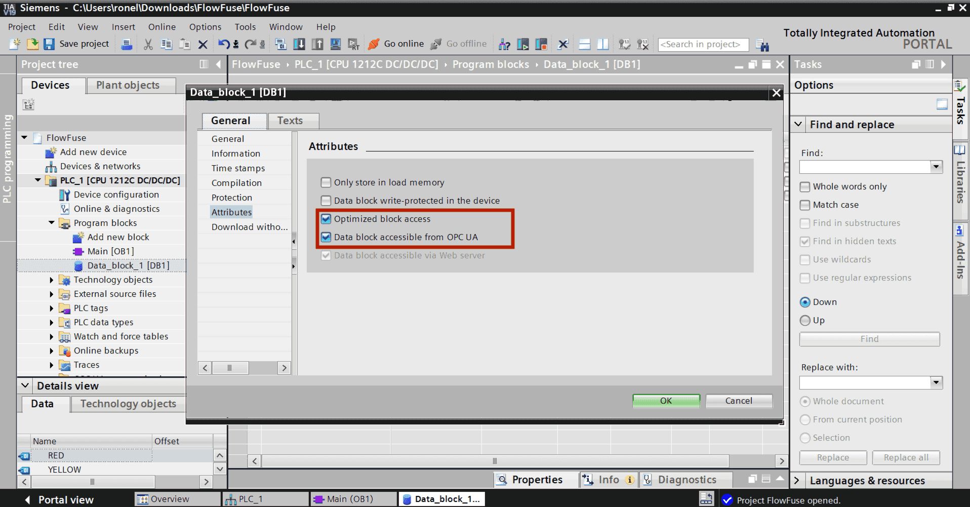
Step 3: Expose Your Data Block Variables
For OPC UA to access your data blocks, you need to mark them as accessible.
First, enable OPC UA access on your data blocks (required for all methods):
- Open your data block in TIA Portal
- Right-click on the data block name in the project tree
- Select Properties
- Go to the Attributes tab
- Check Accessible from HMI/OPC UA and Optimized Block Access
- Click OK
If using S7-1500 with standard SIMATIC server interface:
You're done. All variables in data blocks marked as accessible are now automatically available through OPC UA.
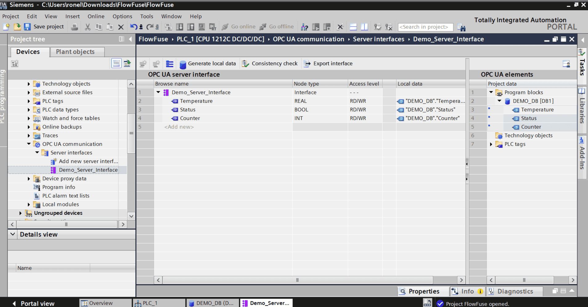
If using manual server interface (S7-1200 or S7-1500):
You need one more step to add specific variables to your server interface:
- In the project tree, expand OPC UA communication
- Expand your server interface
- Drag and drop variables from the OPC UA elements panel (on the right) into your server interface table
- Alternatively, right-click Variables and select Add new variable, then browse to select them
Compile and download:
- Click Compile in TIA Portal
- Download the program to your PLC
Your OPC UA server is now running with the exposed variables ready for access.
Step 4: Install OPC UA Client in FlowFuse
Now switch to your FlowFuse instance to set up the connection to your PLC.
- Open your FlowFuse editor
- Click the menu icon (three horizontal lines, top right)
- Select Manage palette
- Go to the Install tab
- In the search box, type
node-red-contrib-opcua - Find the package in the results and click Install
- Confirm the installation when prompted
- Close the palette manager
The OPC UA nodes will now appear in your node palette on the left side under the "opcua" category.
Step 5: Configure OPC UA Connection
Create a new flow to connect to your PLC and read data.
- Drag an OpcUa-Client node onto your canvas
- Double-click it to open the configuration
- Click the pencil icon next to Endpoint to add a new connection
- Enter the endpoint URL:
opc.tcp://[YOUR_PLC_IP]:4840- Replace
[YOUR_PLC_IP]with your actual PLC IP address (e.g.,opc.tcp://192.168.1.10:4840)
- Replace
- Set Security Policy to None
- Set Security Mode to None
- Under Authentication, select Anonymous
- Click Add to save the endpoint
- Click Done to close the node configuration
Your OPC UA client is now configured to connect to your PLC.
Step 6: Browse Available Variables
Now it's time to discover what's actually available on your PLC. Think of this like opening a file explorer to see what's inside.
- Drag an Inject node onto your canvas
- Drag an OpcUa-Browser node onto the canvas
- Drag a Debug node onto the canvas
- Connect the Inject node to the OpcUa-Browser node, then connect the OpcUa-Browser node to the Debug node
- Double-click the OpcUa-Browser node to open its configuration
- In the Endpoint dropdown, select the connection you created in Step 5
- Leave the Action field set to browse
- Click Done
- Click Deploy in the top-right corner
- Click the inject node button
- Open the Debug panel on the right side
- You'll see a structured tree showing everything your PLC is sharing
Step 7: Read Your First Variable
Let's prove this actually works by reading real data from your PLC.
- Drag an Inject node onto your canvas
- Double-click the Inject node to configure it
- Change Repeat from "none" to interval
- Set it to repeat every 5 seconds
- In the Topic field, enter the NodeId you copied (e.g.,
ns=3;s="Demo_Datablock"."Temperature") - Click Done
- Drag an OpcUa-Client node onto the canvas
- Double-click the OpcUa-Client node to open its configuration
- Select your endpoint from the Endpoint dropdown
- Change Action to read
- Click Done
- Drag a Debug node onto the canvas
- Double-click the Debug node
- Change the output to complete msg object
- Click Done
- Connect the Inject node to the OpcUa-Client node, then connect the OpcUa-Client node to the Debug node
- Click Deploy
- Open the Debug panel on the right side
- You'll see messages appearing every 5 seconds with your variable's value in
msg.payload
Try changing the value in your PLC through TIA Portal and watch the updates appear in FlowFuse. No memory addresses, no offset calculations, just the variable name.
To explore more OPC UA capabilities like subscribing to value changes, writing data back to your PLC, and working with complex data types, check out our article.
Scale Your Industrial Applications with FlowFuse
You've successfully read data from your Siemens PLC, but FlowFuse does much more than connect to a single device. The platform helps you build complete industrial applications that connect to any equipment, collect and transform data from across your factory floor, visualize it in real-time dashboards, and take automated actions based on what's happening in your operation.
FlowFuse makes deployment and management simple, even at scale. Develop your application once, then deploy it to thousands of edge devices across multiple facilities. Manage all your instances from one central platform—push updates, monitor performance, and troubleshoot remotely without visiting each site. Built-in security features protect your industrial data, while horizontal and vertical scaling ensures your applications grow with your business needs.
Whether you're building a predictive maintenance system, a production monitoring dashboard, or a complete MES solution, FlowFuse provides the unified platform to connect, collect, transform, visualize, and act on your industrial data.
Ready to scale beyond a single PLC? Book a demo to see how FlowFuse can transform your industrial operations.
Discuss your use case with our team
See how FlowFuse can support your architecture, integrations, and deployment needs.
About the Author
Sumit Shinde
Technical Writer
Sumit is a Technical Writer at FlowFuse who helps engineers adopt Node-RED for industrial automation projects. He has authored over 100 articles covering industrial protocols (OPC UA, MQTT, Modbus), Unified Namespace architectures, and practical manufacturing solutions. Through his writing, he makes complex industrial concepts accessible, helping teams connect legacy equipment, build real-time dashboards, and implement Industry 4.0 strategies.
Table of Contents
- Why Reading Optimized Data Blocks Is Challenging
- The Solution: OPC UA
- Prerequisites
- Step 1: Activate OPC UA Server on Your PLC
- Step 2: Add OPC UA Server Interface
- Step 3: Expose Your Data Block Variables
- Step 4: Install OPC UA Client in FlowFuse
- Step 5: Configure OPC UA Connection
- Step 6: Browse Available Variables
- Step 7: Read Your First Variable
- Scale Your Industrial Applications with FlowFuse